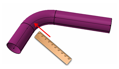
How to measure a tube's bend radius on an isolated body.
If you have ever worked with an imported geometry of a tube, you probably know, that CATIA doesn't provide any tool to measure a bend radius. If there is no centerline, measuring a bend radius or centerline radius requires an extra geometry.
Our target is to create an UDF, which can be used for measuring bend radius, center line radius and bend angle of a dead geometry of a tube.
1. Let's start with a new CATPart, name it Bend Radius. Create 3 GeoSets, name them Tube, Inputs and Bend Radius Measuring.
2. In the Tube GeoSet define 3 points at any reasonable coordinates. Using these three points create a polyline and assign a radius - Fig.1.
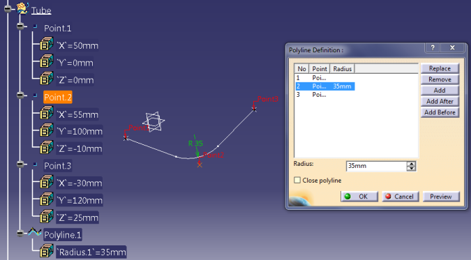 |
| Fig.1 |
3. Now create a swept surface along the polyline. Profile type - Circle, Subtype - Center and radius, assign any reasonable radius, in my case it is 10mm.
4. Go to Input GeoSet and Extract two edges of the surface like it is shown on the Fig.2.
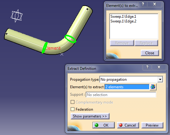 |
| Fig.2 |
5. Isolate the two extracted edges. Now the Inputs GeoSet should contain two isolated circles. The problem is that sometimes CATIA may not recognize these edges as circles on imported geometry, therefore it is better to use any curve as an imput. To turn the two circle into curves use Curve Smooth command (Insert>Operations) - Fig.3. Isolate both curves and delete the circles, now the Inputs should contain two isolated curves.
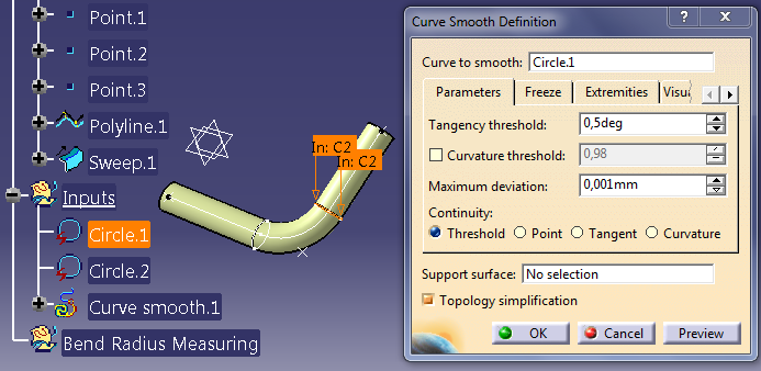 |
| Fig.3 |
6. Now go to the Bend Radius Measuring and create a new GeoSet in it, name it Curve 1. Using one of the input, create a point on curve, see more details on Fig.4.
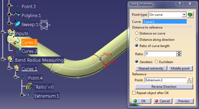 |
| Fig.4 |
7. Create two more points on the same curve. As a reference use the point from the previous step. Ratio values for these two points are 0.333 and 0.666. Three equispaced points have been created on the curve. Use these points to create a circle, type - three points, circle should be closed. Using this circle as a reference, create another point, type Circle / Sphere / Elypse center, to get the center point of the circle.
8. Create a plane using three equispaced points - Fig.5.
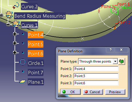 |
| Fig.5 |
9. Use this plane and the center point of the circle to create a new line - Fig.6.
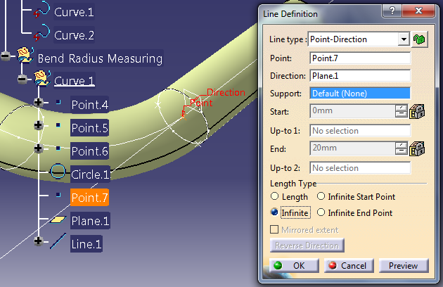 |
| Fig.6 |
10. Curve 1 GeoSet is ready to duplicate it (Fig.7). To duplicate a GeoSet select it [1], use command Duplicate Geometrical Set [2], in the new window choose the destination [3], then select the second curve from the Inputs GeoSet, click OK. Name the new GeoSet - Curve 2.
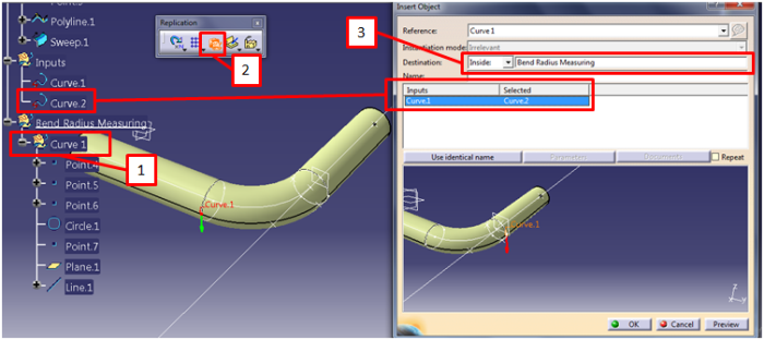 |
| Fig.7 |
11. Using the two lines create a plane - Fig.8.
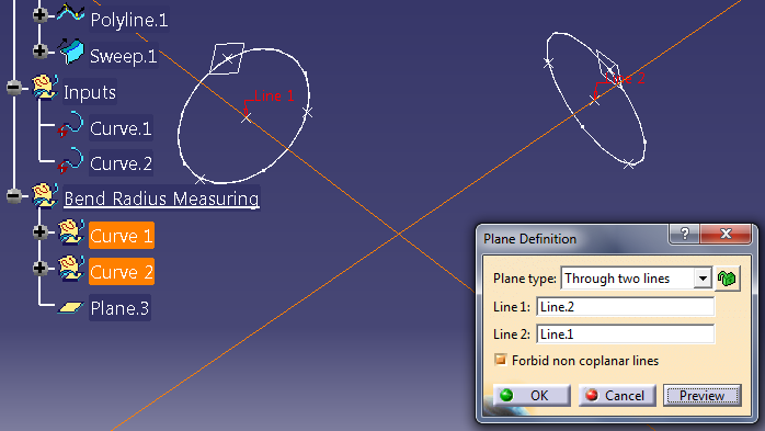 |
| Fig.8 |
12. Use this plane, center point and line from Curve 1 GeoSet to create another line - Fig.9. It has to be normal to the line form Curve 1 GeoSet. Create a line in the same way for the second curve.
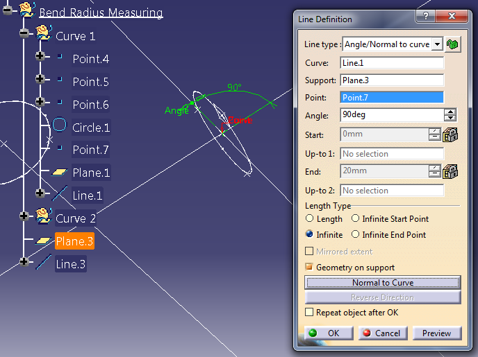 |
| Fig.9 |
13. Intersection of these two lines is the center point of the bend radius (yellow). Name this point - Center Point - Fig.10.
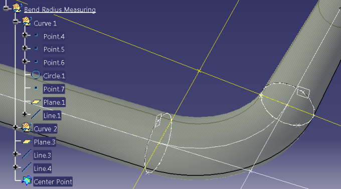 |
| Fig.10 |
14. Create another intersection, like it is shown on Fig.11. Result of this intersection is a multiple result, it means it has more than one solution. In Multi-Result Management window select option - keep only one sub-element using a Near. As a reference element use the Center Point.
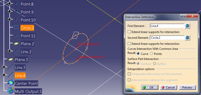 |
| Fig.11 |
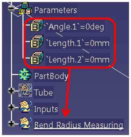
15. It was the last geometry we need. Now create three parameters - two length type and one angle. Drag&drop them to the Bend Radius Measuring Geo Set - Fig.12.
 |
| Fig.12 |
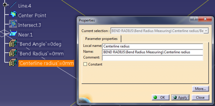
16. Edit their properties and change their local names - Fig.13.
 |
| Fig.13 |
17. Next step is to create formluas for these parameters. Add a formula to the Bend Angle parameter (Fig.14). The formula measures the angle between two lines. Line.3 and Line.4 are the yellow lines created in step number 12.
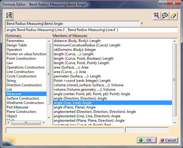 |
| Fig.14 |
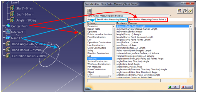
18. Formula of the Bend Radius parameter is shown of Fig.15.
 |
| Fig.15 |
19. Smilar formula has to be created for the last parameter, use the Center Point and one of the center points of the input curves - Fig.16.
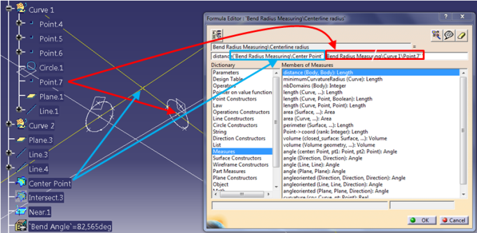 |
| Fig.16 |
20. New formulas have been created, drag&drop them to the Bend Radius Measuring Geo Set - Fig.17.
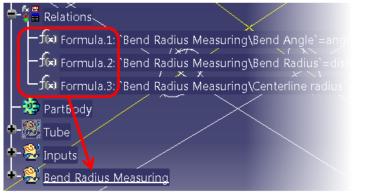 |
| Fig.17 |
21. Hide all the geometry and show only Center Point, Inputs and surface of the tube - Fig.18.
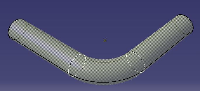 |
| Fig.18 |
22. In this step an UDF will be created, go to
Insert > Knowledge Templates > User Feature. Select the Bend Radius Measuring Geo Set, curve.1 and curve.2 should appear in Inputs of components - Fig.19.
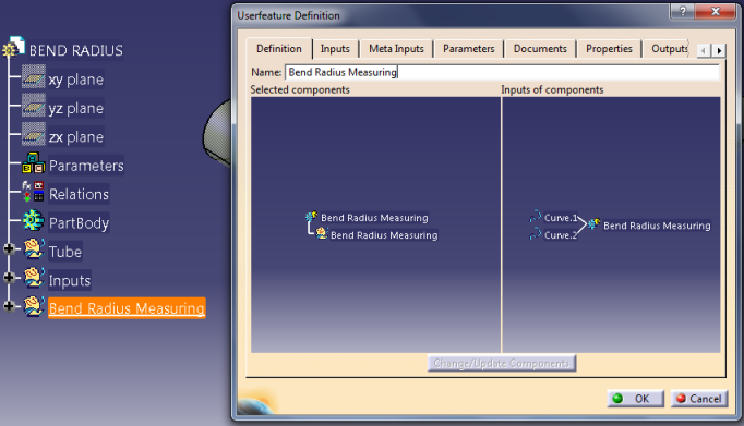 |
| Fig.19 |
23. Go to the Parameters Tab and the three parameters created in step number 15. Publish these parameters and modify their names - Fig.20.
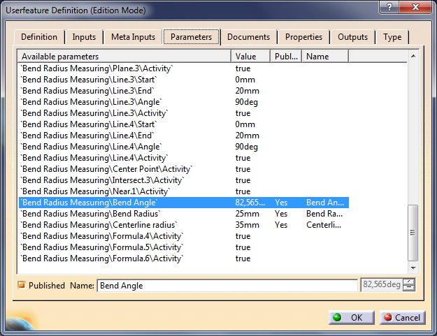 |
| Fig.20 |
24.Go to the tab Outputs and make sure that the main result is the Center Point, if it is not, replace the main result with it - Fig.21. You can also go to the Properties tab to change the icon of this UDF. Click OK.
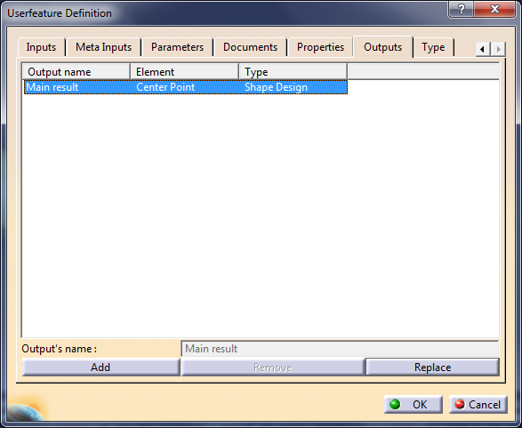 |
| Fig.21 |
25. Save the file and close it.
26.
To use the UDF create a new file and another tube in it. Go to Insert®Instantiate From Document and select the CATPart from previous point. In Insert Object window choose a destination and as an input select two curves - Fig.22.
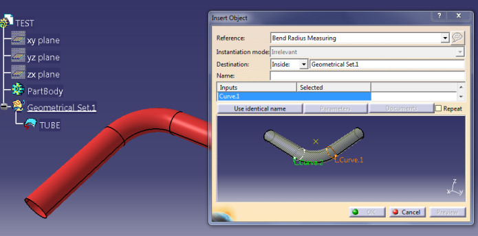 |
| Fig.22 |
27. The bend has been measured and the parameters have been created - Fig.23.
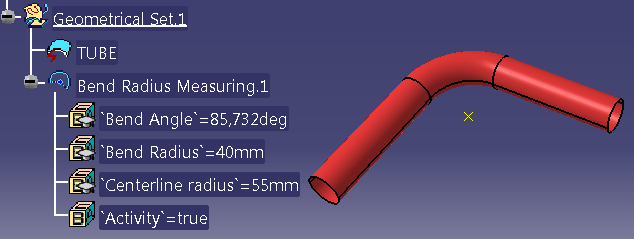 |
| Fig.23 |